Wiring & Connections
The OWL’s relay outputs can switch any 12V device, making it versatile for spot spraying, demonstrations, educational setups, and custom applications.
What Can Be Connected
The OWL provides 4 relay channels, each capable of switching 12V DC devices up to 10A. Any device that operates on 12V can be controlled.
Spray Applications
Device |
Use Case |
|---|---|
Solenoid valves |
Spot spraying herbicide, liquid fertiliser |
Electric ball valves |
Higher flow applications |
Diaphragm pumps |
On-demand spraying |
Demonstration & Educational
For testing, demonstrations, or educational purposes, you can connect visual indicators instead of (or alongside) spray equipment:
Device |
Use Case |
|---|---|
12V LED strips |
Visual indication of detection zones |
12V indicator lights |
Dashboard-style detection feedback |
12V buzzers |
Audio feedback for detections |
12V light bulbs |
High-visibility demonstration |
Tip
Educational setups using lights are excellent for:
Training operators before field deployment
Demonstrating detection algorithms at workshops
Testing and calibrating without using spray chemicals
Indoor demonstrations at agricultural shows
Other Applications
Device |
Use Case |
|---|---|
Electric actuators |
Targeted tillage, mechanical weeding |
Ignition modules |
Spot flaming systems |
12V motors |
Custom mechanical systems |
Relay modules |
Switching higher voltage/current devices |
Relay Specifications
Parameter |
Value |
|---|---|
Number of channels |
4 |
Switching voltage |
12V DC |
Maximum current per channel |
10A |
Actuation type |
Normally Open (NO) |
Control |
GPIO-driven via Raspberry Pi |
Wiring Solenoids
Pin Mapping
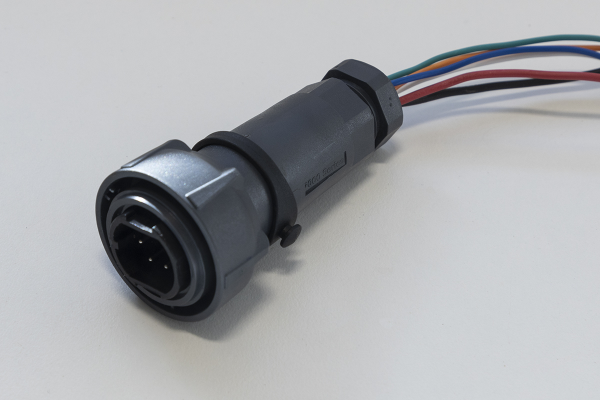
Each relay output corresponds to a coloured wire on the Bulgin connector:
Relay |
GPIO Pin |
Wire Colour |
Bulgin Pin |
|---|---|---|---|
Relay 0 |
GPIO 13 |
Blue |
Pin 1 |
Relay 1 |
GPIO 15 |
Green |
Pin 2 |
Relay 2 |
GPIO 16 |
Orange |
Pin 3 |
Relay 3 |
GPIO 18 |
White |
Pin 4 |
12V Power |
- |
Red |
Pin 5 |
Ground |
- |
Black |
Pin 6 |
Basic Wiring
GND wire of your device connects to the ground pin on the Bulgin plug (same wire used for GND from 12V power source)
Positive wire of your device connects to one of the relay outputs (Blue, Green, Orange, or White)
Warning
The relay switches the ground side of the circuit. Your 12V device should have its positive terminal connected directly to the 12V supply, and the negative terminal connected through the relay.
Wiring Diagram

Six-Way Harness
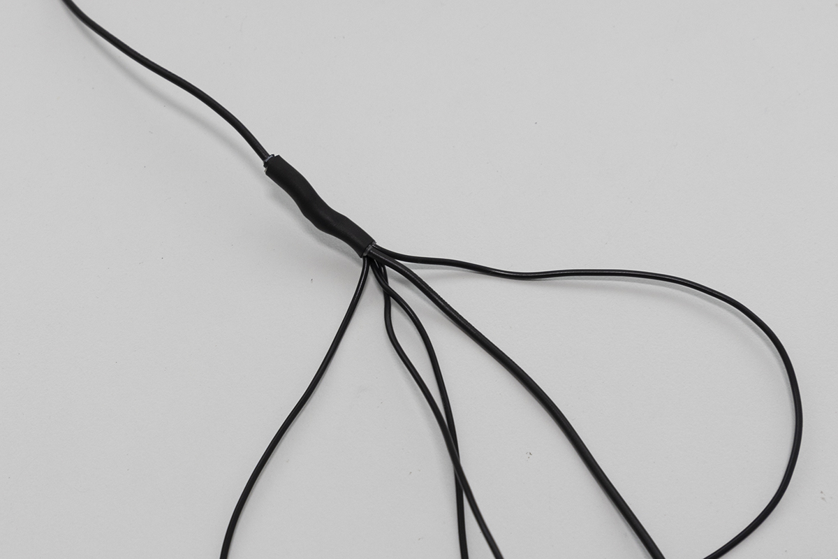
The easiest wiring method is to create a six-way harness:
One end connects to the Bulgin plug
One wire connects to source power GND (shared ground)
Four remaining wires connect to your devices (solenoids, lights, etc.)
Bulgin plug |
Ground wiring harness |
|---|---|
Example: Indicator Light Setup
For demonstrations or testing, wire 12V LED indicators to each relay:
Parts needed:
4x 12V LED indicator lights (panel mount)
Wire (appropriate gauge for your LEDs)
Connectors or solder
Wiring:
Connect all LED positive terminals to 12V supply
Connect each LED negative terminal to a separate relay output:
LED 1 → Blue wire (Relay 0)
LED 2 → Green wire (Relay 1)
LED 3 → Orange wire (Relay 2)
LED 4 → White wire (Relay 3)
When OWL detects vegetation in a zone, the corresponding LED illuminates.
Configuration
Relay Timing
Adjust how long relays stay activated after detection:
[System]
actuation_duration = 0.15
delay = 0
relay_num = 4
Parameter |
Default |
Description |
|---|---|---|
|
0.15s |
How long relay stays ON after detection |
|
0s |
Delay between detection and relay activation |
|
4 |
Number of relay channels to use |
Detection Zones
Each relay corresponds to a horizontal zone in the camera’s field of view. When vegetation is detected in a zone, the corresponding relay activates.
Camera View:
┌─────────┬─────────┬─────────┬─────────┐
│ Zone 0  │ Zone 1  │ Zone 2  │ Zone 3  │
│ Relay 0 │ Relay 1 │ Relay 2 │ Relay 3 │
│ (Blue)  │ (Green) │ (Orange)│ (White) │
└─────────┴─────────┴─────────┴─────────┘
Safety Considerations
Warning
Electrical Safety
Ensure all connections are secure and insulated
Use appropriate wire gauge for your current requirements
Include inline fuses for protection
Keep wiring away from moving parts and heat sources
Warning
Spray Equipment
Follow all chemical handling guidelines
Ensure proper PPE when working with herbicides
Test systems with water before using chemicals
Verify solenoid ratings match your operating pressure
Recommended Solenoids
For spot spraying applications:
Component |
Recommendation |
|---|---|
Solenoid valves |
Goyen 3QH/3662 with Teejet body |
Spray tips |
Teejet TP4003E-SS (40°, flat fan, stainless steel) |
Strainer |
TeeJet 50 mesh |
See Use Cases for complete spray system specifications.
Next Steps
Use Cases - Complete application examples
Operation Guide - Detection algorithms and performance
Configuration - Full parameter reference