Compact OWL
The new OWL design is more compact, inside either an extruded aluminium enclosure or 3D printed housing. It offers improved water and dust resistance, plus ease of assembly and longevity. This design is recommended for production use.
The parts list is substantially reduced:
Compact OWL Enclosure Options
Compact OWL - Extruded Aluminium Enclosure |
Compact OWL - 3D Printed Enclosure |
|---|---|
Hardware List
Component |
Quantity |
Link |
|---|---|---|
Enclosure |
||
OFFICIAL OWL ENCLOSURE - aluminium |
1 |
TBD |
Extrusion - 3D printed |
1 |
|
Front plate |
1 |
|
Tray |
1 |
|
Back plate - Amphenol, Adafruit RJ45 |
1* |
|
Back plate - Amphenol only |
1* |
|
Back plate - 16 mm cable gland |
1* |
|
Lens mount |
1 |
|
Camera mount |
1* |
|
Computing |
||
Raspberry Pi 5 4GB (or Pi 4 or 3B+) |
1 |
|
64GB SD Card (min. 16 GB) |
1 |
|
Green-on-Green accelerator (optional, see Green-on-Green) |
1 |
Raspberry Pi AI Hat+ |
Camera (choose one) |
||
RECOMMENDED: Raspberry Pi Global Shutter Camera |
1 |
|
CCTV 6mm Wide Angle Lens |
1 (GS or HQ only) |
|
Arducam 3.2mm CS-mount lens (alternative — wider FOV at low mount height) |
1 (GS or HQ only) |
|
SUPPORTED: Raspberry Pi 12MP HQ Camera |
1 |
|
SUPPORTED: Raspberry Pi Camera Module 3 |
1 |
|
SUPPORTED: Raspberry Pi V2 Camera (NOT RECOMMENDED) |
1 |
|
⚠️NOTE⚠️ If you use the RPi 5, make sure you have the right camera cable |
1 |
|
Power Management * items only needed in place of OWL driver board |
1 |
|
OFFICIAL OWL DRIVER BOARD (recommended — incl. power mgmt, relay control, hardware enable switch for the nozzles) |
1 |
TBD |
* 5V 5A Step Down Voltage Regulator |
1 |
|
* 4 Channel, Relay Control Board HAT |
1 |
|
* Jumper Wire |
1 |
|
Amphenol Fathomlock Connector - 6 pin connector (FLS6BS10N3W3P03) |
1 |
|
Amphenol Fathomlock Connector - 6 pin plug (FLS710N3W3S03) |
1 |
|
Adafruit RJ45 Cable Gland |
1 |
|
16mm Cable Gland |
1 |
|
Miscellaneous |
||
3 - 16V Piezo Buzzer (optional) |
1 |
|
Brass Standoffs - M2/3/4 (required for HAT/driver board) |
Kit |
|
Wire - 20AWG (red/black/green/blue/yellow/white) |
1 roll each |
3D Printed Enclosure Requirements
⚠️NOTE⚠️ The 3D printed version requires the additional purchase of:
M2, M3 and M4 threaded inserts + M2, M3 and M4 hex head screws
Compact OWL - Hardware Assembly
The OWL driver board is the recommended path. It’s more compact and easier to install than the generic relay HAT route, combines the relay control, power supply and wiring on one board, and adds a hardware enable switch for the nozzles — so you can disable spraying from the device itself without shutting down the OWL or relying on software.
With the driver board, no soldering is required. The generic Pi relay HAT route is supported as an alternative when the driver board isn’t available — that path needs a separate voltage regulator soldered in to provide the 5V @ 5A required for the Raspberry Pi 5, or up to 3A for the older models.
There are two options for the enclosure. The 3D printed enclosure and the official OWL extruded aluminium enclosure. Both share a 3D printed tray and the same components. The 3D printed version allows you to make a start without needing to buy bespoke components if you have access to a 3D printer.
The 3D model files for the printed enclosure can be downloaded from the 3D Printing page.
The Official OWL Enclosure will be available for purchase through the OWL store soon.
Step 1 - enclosure, camera and mounts
The internal tray is the same for both the extruded aluminium or 3D printed enclosures. The 3D printed tray suits the Raspberry Pi HQ Camera and the Global Shutter Camera. A separate mount is available for the Camera Module 3. Details are provided below.
Begin camera installation by removing the adapter ring and fitting the lens. The camera will not focus with this ring.
Global Shutter camera with adapter ring atached |
Adapter ring removed |
|---|---|
Mount the camera to the front of the tray using M2.5 standoffs. The Global Shutter camera requires slightly longer standoffs to get past the plastic backing cover. Run the ribbon cable over the top of the tray (as pictured)
Internal tray |
Mounting the camera |
Mounting the camera |
|---|---|---|
Once the camera is secured, mount the Raspberry Pi using 4 x M2.5 x 5mm long standoffs. To secure the Pi, use 4 x 15mm standoffs. These will be used to mount the HAT.
Raspberry Pi 4B mounted on tray |
|---|
3D printed enclosure
The 37 mm UV lens filter is installed on the faceplate with 8 M2 heat-set threaded inserts and M2 hex head screws. Add the 1.6mm nitrile rubber o-ring cord to the internal channel on the lens mount. Firmly press the 37 mm UV lens filter into the channel on the faceplate.
Tighten down the 8 M2 screws in a cross pattern (similar to how a car tyre is installed), to avoid cracking the 3D printed mount.
Faceplate |
Lens mount |
Lens fitted with o-ring |
|---|---|---|
The 3D printed enclosure also supports the mounting of the Camera Module 3 with an extra 3D printed part. Using M2 threaded inserts in the faceplate, mount the plate with approx. 5mm long M2 standoffs. Route the camera ribbon cable over the top.
Camera mounted on backplate |
Faceplate with standoffs and backplate |
Assembled |
|---|---|---|
Step 2 - connecting the Official OWL HAT
The OWL Hat simply fits over the GPIO pins and is mounted using the 4 x 15 mm standoffs installed in the previous step. Secure the HAT with 4 x 2.5mm screws and tighten down.
PWM or GPIO control is selected with four jumper pins (in blue below).
Fitted Official OWL HAT |
OWL Hat jumpers |
GPIO pin assignment |
|---|---|---|
The default option is for GPIO control as pictured. By default the OWL HAT is wired as shown above:
[Relays]
# defines the relay ID (left) that matches to a boardpin (right) on the Pi.
# Only change if you rewire/change the relay connections.
0 = 13
1 = 15
2 = 16
3 = 18
The final jumper pin Pi Power Supply Enable connects the Raspberry Pi to the 5V provided by the HAT. Only connect this jumper once you want the
Pi to start.
Step 2a - connecting a generic relay HAT
Instead of the Official OWL HAT, a relay control HAT (such as this from PiHut) can be used, with some minor changes to the OWL software. There are many different relay HATs available, so check which is most suitable for your purposes. Be sure to choose one with accessible GPIO pins.
Fit the HAT as recommended by the manufacturer, similar to the below images (source: The PiHut).
HAT |
Installed HAT |
|---|---|
In its default configuration, this specific relay HAT assigns GPIO boardpins 29, 31, 33, and 35 to relays 4 - 1
respectively. This differs to the default OWL configuration, so the [Relays] section of the config file would need to
be updated. Using this board as the example:
[Relays]
# defines the relay ID (left) that matches to a boardpin (right) on the Pi.
# Only change if you rewire/change the relay connections.
0 = 35
1 = 33
2 = 31
3 = 29
However, if you use another relay HAT check the assignment/configuration of relays to boardpins. For reference, use this GPIO guide to help.

Step 2b - connecting the voltage regulator
Without the OWL HAT, 5V power to Pi needs to be supplied separately. We recommend the Pololu 5V 5.5A step down voltage regulator, however, there are many options available.
Solder wires to the input and output of the voltage regulator. Using WAGO connector blocks, connect the input to the 12V from the Amphenol connector. Mount the regulator to the underside of the internal tray using M2 standoffs.
Raspberry Pi 3B+ or 4B
The earlier models of the Raspberry Pi consumer less power (3A @ 5V) than the Raspberry Pi 5 and can be powered over single 5V and GND pins on the GPIO. Use high quality connectors here or consider soldering directly to the GPIO pins on the HAT. A good connection without risk of coming loose, is critical.
You’ll need to solder to pins 2 (5V) and 6 (GND) on the relay HAT. More details provided here from The PiHut (image source).
Raspberry Pi 5
The Raspberry Pi 5 consumes up to 5A @ 5V, so it’s suggested to use 2 x 5V and 2 x GND pins on the Raspberry Pi. Some good information on the topic is provided here.
Using the two 5V outputs from the voltage regulator, solder one +5V wire to pin 2 and another to pin 4 on the GPIO on the HAT relay. Similarly, connect two GND wires from the voltage regulator output to pins 30 and 34. Ensure there is a good solder connection, without any short circuits to neighbouring pins.
The images below are from a Raspberry Pi 5, however, the setup is the same for the 4B and 3B+ models just with one 5V/GND wire.
HAT installation - GPIO |
HAT installation - soldering the 2 x 5V, 2x GND |
HAT Installation - voltage regulator |
|---|---|---|
Step 3 - wiring the connector and HAT
Begin by wiring the Amphenol EcoMate Aquarius receptacle. The connector has 3 x 16 guage connections rated to 13A and 3 x 20 guage rated up to 7.5A (machined) or 5A (stamped). Use the appropriate crimp connections for the 16 and 20 guage connections.
Connections are labeled A - F on the receptacle and should be made in the following order:
+12V (red) - A
GND (black) - E
relay 1 (blue) - B
relay 2 (green) - C
relay 3 (orange) - D
relay 4 (white) - F
Unlike the relay HATs and relay board in the Original OWL, the common ground for the OWL driver board is routed through the board itself, reducing the wiring required. Connect the wires from the back of the connector to each relay, using the above list as a guide. The finished result should appear similar to the images below. Add heat shrink at the end of each wire for neater and more reliable connections.
Connector with wires |
Completed HAT |
Completed HAT mounted on the Pi |
|---|---|---|
Optional Components
OPTIONAL Add a 5V buzzer inside the OWL by mounting it to the corner of the HAT with a screw. Connect the 5 V and ground wires to Raspberry Pi GPIO pins 7 and 9, respectively. The buzzer is useful for identifying when the OWL has started successfully. It isn’t essential to operation.
OPTIONAL Add Kapton tape to the camera cable and internal wiring. Kapton tape is a god insulator and resistant to high temperatures, improving the robustness of the device.
Tray with Kapton tape |
|---|
Step 4 - inserting the tray and closing the device
Software Setup First
⚠️NOTE⚠️ For software installation, you’ll need access to the Raspberry Pi display, and USB ports. We recommend you set up the software prior to completing the build and inserting the tray. Alternatively, flash the SD card with one of the provided owl disk images.
To improve the resistance to dust and water ingression on the 3D printed version, you’ll need to add a 3mm nitrile rubber o-ring around the face- and backplates of the enclosure.
Faceplate with o-ring |
Backplate with o-ring |
|---|---|
Fix the faceplate to the enclosure with the 4 x M4 screws. The 3D printed enclosure will need 4 x M4 threaded inserts set into the plastic on the back and front of the enclosure body. Carefully push the tray into the enclosure on the second row, making sure wires are not caught up on the side.
For the single Amphenol EcoMate Aquarius receptacle, push it through the backplate and tighten down. Fix the backplate to the enclosure.
Front |
Back |
|---|---|
There is a choice of three different backplates, depending on your hardware requirements. They include:
1 x hole for the Amphenol EcoMate Aquarius
2 x holes for the Amphenol EcoMate Aquarius and Adafruit waterproof RJ45 (ethernet) connector
1 x 16mm hole for a 16mm cable gland.
If you would prefer a different arrangement, just get in touch or raise an issue and we can sort it out for you!
Backplate options (aluminium) |
Backplate options (3D printed) |
|---|---|
And you’re all done! Congratulations on building your OWL.
Connecting Solenoids for Spot Spraying
Optional Step - connecting 12V solenoids
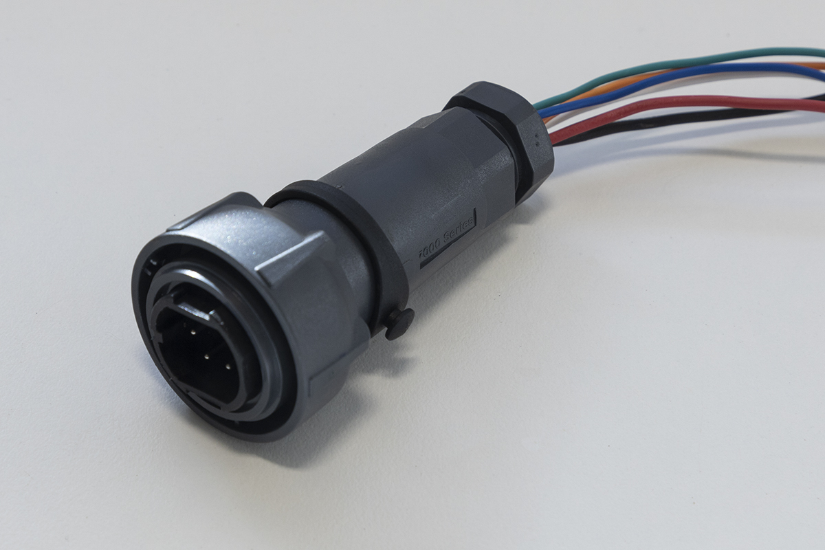
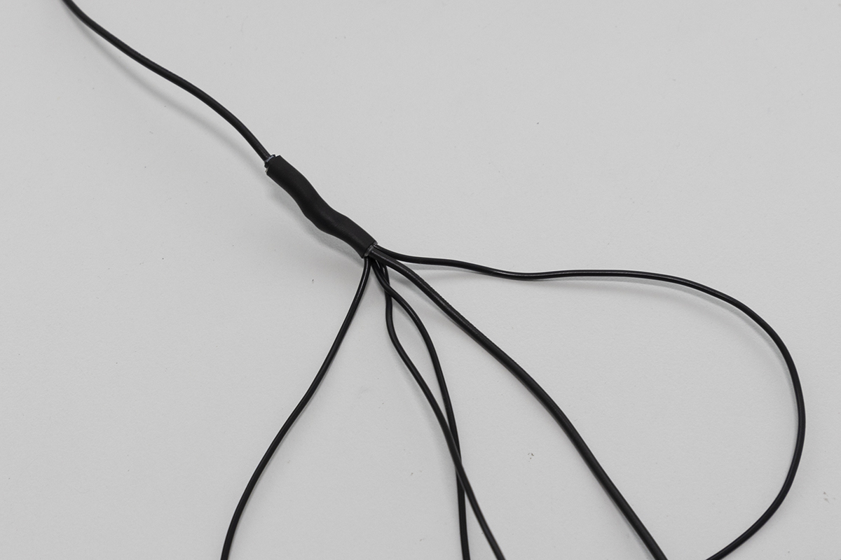
Once you have completed the setup, you now have the opportunity to wire up your own solenoids for spot spraying, targeted tillage, spot flaming or any other targeted weed control you can dream up. To do this, wire the GND wire of your device (it can be any wire if it’s a solenoid) to the ground pin on the Bulgin plug (the same wire used for the GND from the 12V power source) and wire the other to one of the blue, green, orange or white wires on pins 1 - 4. A wiring diagram is provided below. The easiest way to wire them together to the same GND wire is to create a six-way harness, where one end is connected to the plug, one of the five other wires to the source power GND and the remaining four to the solenoids or whatever devices you are driving.

Bulgin plug |
Ground wiring harness |
|---|---|
Next Steps
Congratulations on completing your Compact OWL hardware assembly! Here’s what to do next:
Install the OWL software on your Raspberry Pi to get your detection unit operational.
Configure detection sensitivity, relay timing, and other parameters for your specific use case.
Learn how to operate your OWL in the field, including mounting, alignment, and best practices.
Need replacement parts or want to print your own enclosure? Find all STL files and print settings here.