Original OWL
The original OWL lays out all components in a flat design. It makes the connections and interactions within the system clear. It’s a great educational tool to learn the parts required for a weed detection system and has served in the field as a functional weed detection system for a number of years.
Hardware List
Component |
Quantity |
Link |
|---|---|---|
Enclosure |
||
Main Case (single Bulgin connector) |
1 |
|
Main Case (cable glands) |
1 |
|
Main Cover |
1 |
|
Raspberry Pi Mount |
1 |
|
Relay Control Board Mount |
1 |
|
Voltage Regulator Mount |
1 |
|
Camera Mount |
1 |
|
Enclosure Plug |
1 |
|
Computing |
||
Raspberry Pi 5 4GB (or Pi 4 or 3B+) |
1 |
|
64GB SD Card (min. 16 GB) |
1 |
|
Green-on-Green accelerator (optional, see Green-on-Green) |
1 |
Raspberry Pi AI Hat+ |
Camera (choose one) |
||
RECOMMENDED: Raspberry Pi Global Shutter Camera |
1 |
|
CCTV 6mm Wide Angle Lens |
1 (GS or HQ only) |
|
Arducam 3.2mm CS-mount lens (alternative — wider FOV at low mount height) |
1 (GS or HQ only) |
|
SUPPORTED: Raspberry Pi 12MP HQ Camera |
1 |
|
SUPPORTED: Raspberry Pi Camera Module 3 |
1 |
|
SUPPORTED: Raspberry Pi V2 Camera (NOT RECOMMENDED) |
1 |
|
⚠️NOTE⚠️ If you use the RPi 5, make sure you have the right camera cable |
1 |
|
Power |
||
5V 5A Step Down Voltage Regulator |
1 |
|
4 Channel, 12V Relay Control Board |
1 |
|
M205 Panel Mount Fuse Holder |
1 |
|
Jumper Wire |
1 |
|
WAGO 2-way Terminal Block |
2 |
|
Bulgin Connector - Panel Mount |
1 |
|
Bulgin Connector - Plug |
1 |
|
Micro USB to USB-C adaptor |
1 |
|
Micro USB Cable |
1 |
|
Miscellaneous |
||
12V Chrome LED |
2 |
|
3 - 16V Piezo Buzzer |
1 |
|
Brass Standoffs - M2/3/4 |
Kit |
|
M3 Bolts/Nuts |
4 each or Kit |
|
Wire - 20AWG (red/black/green/blue/yellow/white) |
1 roll each |
|
Optional |
||
Real-time clock module |
1 |
Original OWL - Hardware Assembly
Safety Warning
⚠️NOTE⚠️ All components listed above are relatively “plug and play” with minimal soldering or complex electronics required. Follow these instructions carefully and triple check your connections before powering anything on to avoid losing the magic smoke and potentially a few hundred dollars. Never make changes to the wiring on the detection unit while it is connected to 12V and always remain within the safe operating voltages of any component.
A video guide is available for the Original OWL assembly.
Before starting, have a look at the complete wiring diagram below to see how everything fits together. The LEDs, fuse and Bulgin connector are all mounted on the rear of the OWL unit, rather than where they are located in the diagram. If you prefer not to use or can’t access a Bulgin connector, there is a separate 3D model design that uses cable glands instead.

Step 1 - enclosure and mounts
Assembling the components for an OWL unit requires the enclosure and mounts as a minimum. These can be 3D printed on your own printer or printed and delivered from one of the many online stores that offer a 3D printing service. Alternatively, you could create your own enclosure using a plastic electrical box and cutting holes in it, if that’s easier. We’ll be assuming you have printed out the enclosure and associated parts for the rest of the guide, but please share your finished designs however they turn out!
The first few steps don’t require the enclosure so you can make a start right away, but while you’re working on getting that assembled, make sure you have the pieces printing, they’ll be used from Step 4. For a complete device, you’ll need: 1 x base, 1 x cover, 1 x RPi mount, 1 x relay mount, 1 x regulator mount, 1 x camera mount and 1 x plug.
Step 2 - soldering
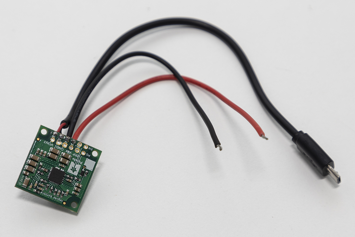
There are only a few components that need soldering, including the fuse and voltage regulator:
Soldering of voltage regulator pins
Soldering of 12V input wires to voltage regulator pins
Soldering of 5V output wires to voltage regulator pins (micro USB cable)
Soldering of red wire to both fuse terminals
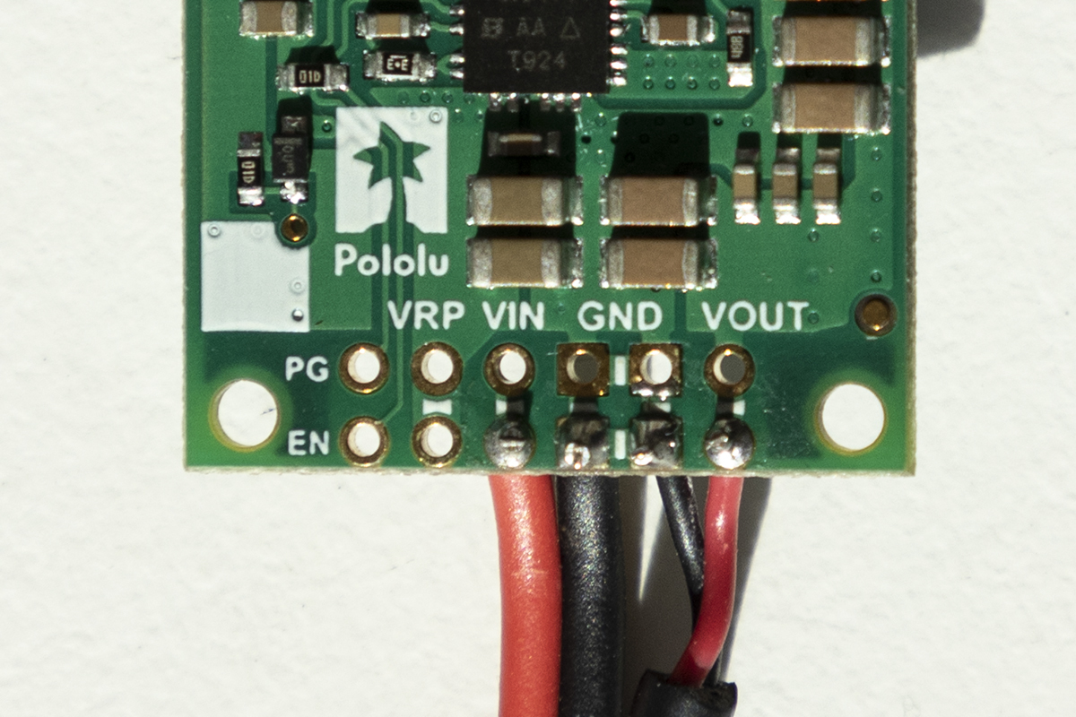
Carefully check which pins on the voltage regulator correspond to 12V in, GND in, 5V out and GND out prior to soldering.
To solder the Micro USB cable to the voltage regulator output, you’ll need to cut off the USB A end so you are left with approximately 10cm of cable. Using the wire strippers or a sharp box cutter/knife, remove the rubber sheath around the wires. If you have a data + charging cable you should see red, green, white and black wires. The charging only cables will likely only have the red and black wires. Isolate the red (+5V) and black (GND) wires and strip approximately 5mm off the end. Solder the red wire to the positive output on the voltage regulator and black wire to the GND pin. Once you have finished, it should look like the first panel in the figure below.
Soldering Safety
⚠️NOTE⚠️ Soldering can burn you and generates potentially hazardous smoke! Use appropriate care, fume extractors and PPE to avoid any injury. If you’re new to soldering, read through this guide, which explains in more detail how to perfect your skills and solder safely.
⚠️NOTE⚠️ When soldering, it’s best to cover the exposed terminals with glue lined heat shrink to reduce the risk of electrical short circuits.
Voltage regulator |
Voltage regulator pins |
Fuse |
|---|---|---|
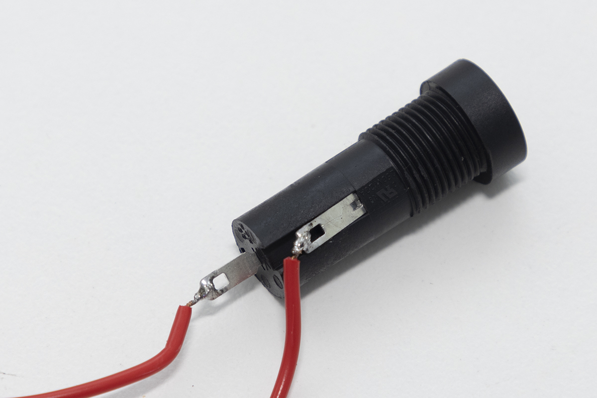
Once the two red wires are soldered to the fuse, the fuse can be mounted on the rear panel of the OWL base. One wire will be connected to the Bulgin plug (next step) and the other to the Wago 2-way block.
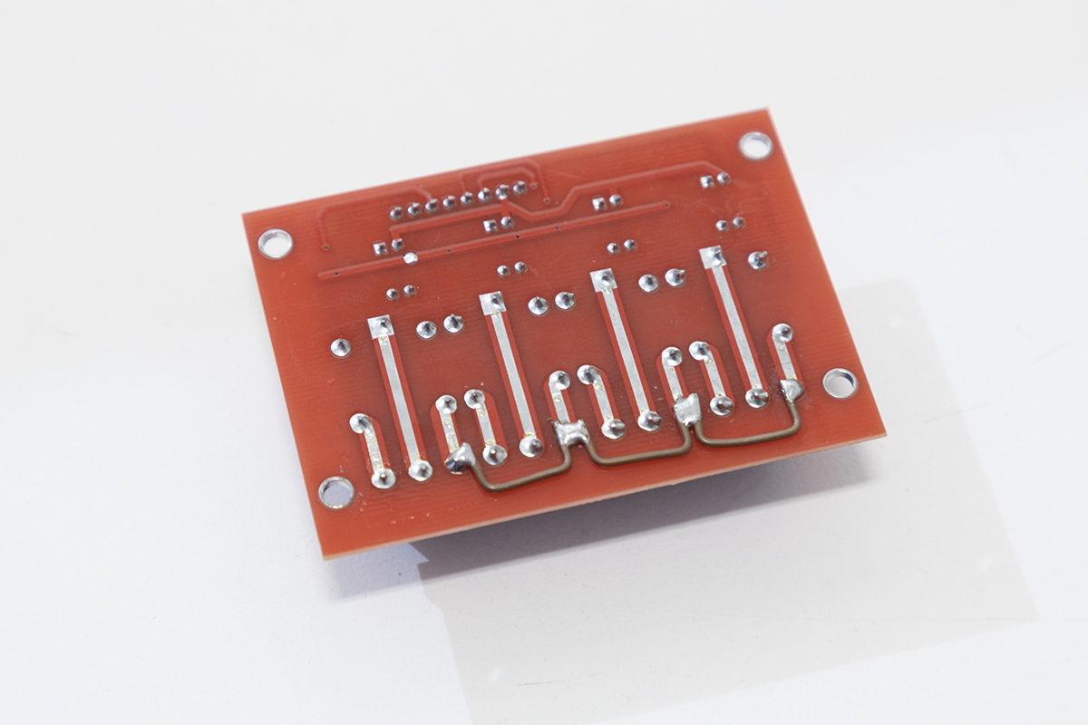
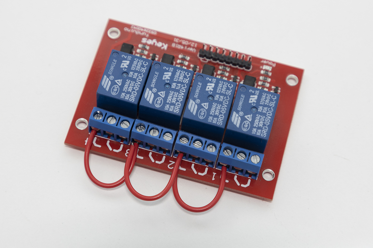
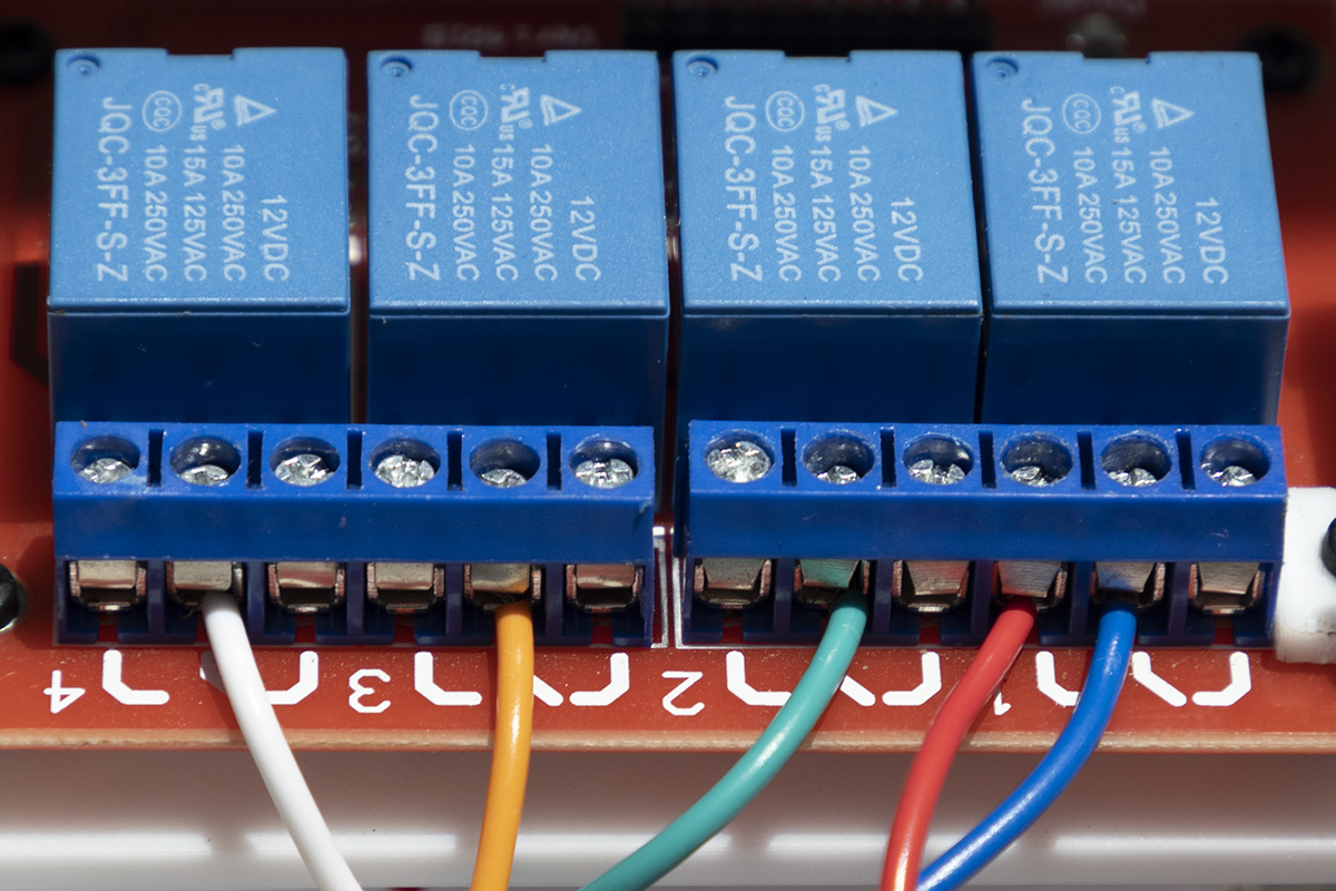
For neater wiring you can also solder jumpers between all the normally open (NO) pins on the base of the relay board, but this is optional. If you don’t solder these connections, make sure you connect wire using the screw terminals instead. Photos of both are provided below.
Soldered |
Screw terminals |
|---|---|
The other wires requiring soldering are joins between the buzzer and jumper wires for easy connection to the GPIO pins and from the LEDs to the power in/jumper wires.
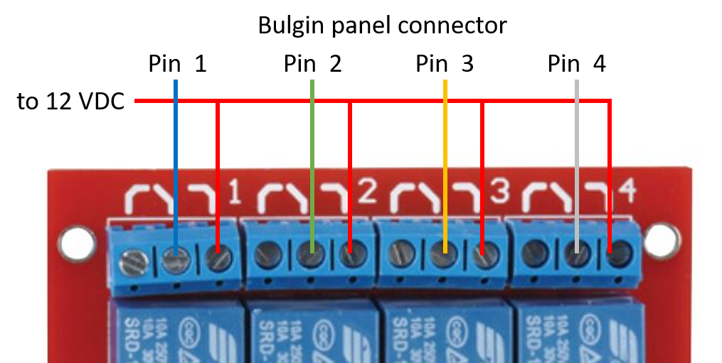
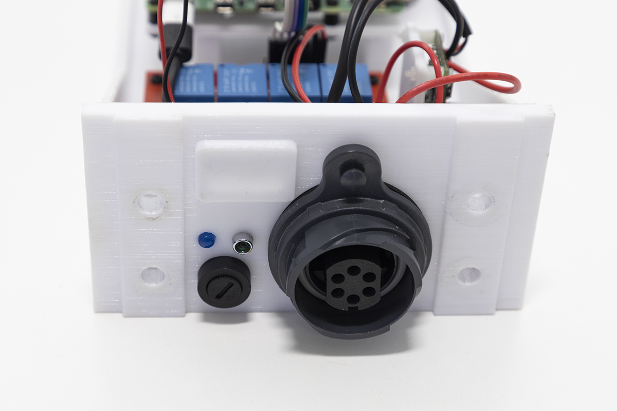
Step 3 - wiring up Bulgin connector
Next we’ll need to wire the output relay control and input 12V wires to the Bulgin panel mount connector. Fortunately all pins are labelled, so follow the wire number table below. This will need to be repeated for the Bulgin plug as well, which will connect your solenoids or other devices to the relay control board.
The process is:
Connect all wires to Bulgin connector using the screw terminals
Mount the connector to the rear panel
Leave at least 10cm of wire so it can be connected to the relay board and other connections later.
Bulgin terminal number |
Wire connection |
|---|---|
1 |
Blue wire - connects to centre terminal (common) on relay 1 |
2 |
Green wire - connects to centre terminal (common) on relay 2 |
3 |
Orange wire - connects to centre terminal (common) on relay 3 |
4 |
White wire - connects to centre terminal (common) on relay 4 |
5 |
Red 12VDC - connects to fuse wire already soldered. Make sure wire is the right length when mounted. |
6 |
Black GND - connects to Wago 2-way terminal |
Cable Gland Alternative
⚠️NOTE⚠️ Skip this step if you’re using cable glands.
Once all the wires have been connected you can now mount the Bulgin connector to the OWL base.
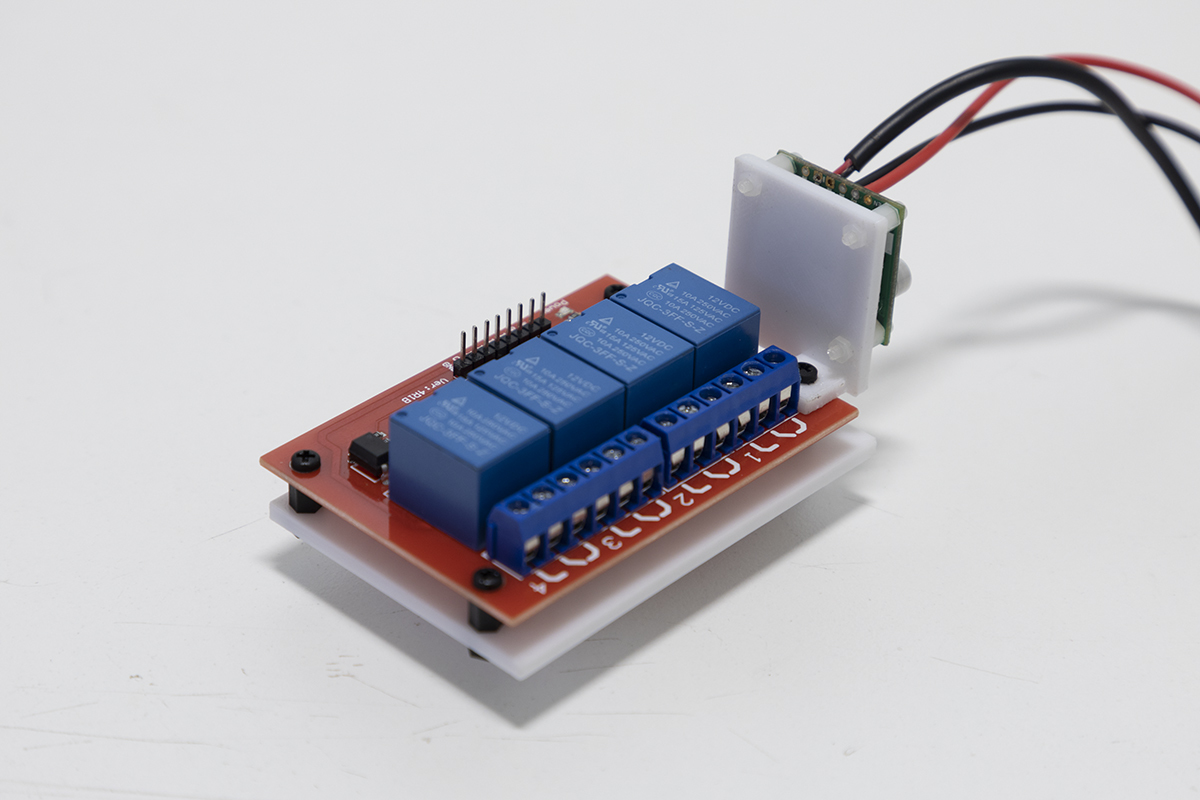
Step 4 - mounting the relay control board and voltage regulator
Attach the relay control board to the 3D printed relay control board mount using 2.5 mm standoffs. Attach the voltage regulator to the 3D printed voltage regulator mount with 2 mm standoffs. The mounted voltage regulator can then be mounted to one corner of the relay control board. The relay board and voltage regulator can then be installed in the raised slots in the OWL base.
Standoff Sizes
⚠️NOTE⚠️ Use 2.5 mm standoffs for mounting the relay control board to its base. Use 2 mm standoffs to mount the voltage regulator to its base.
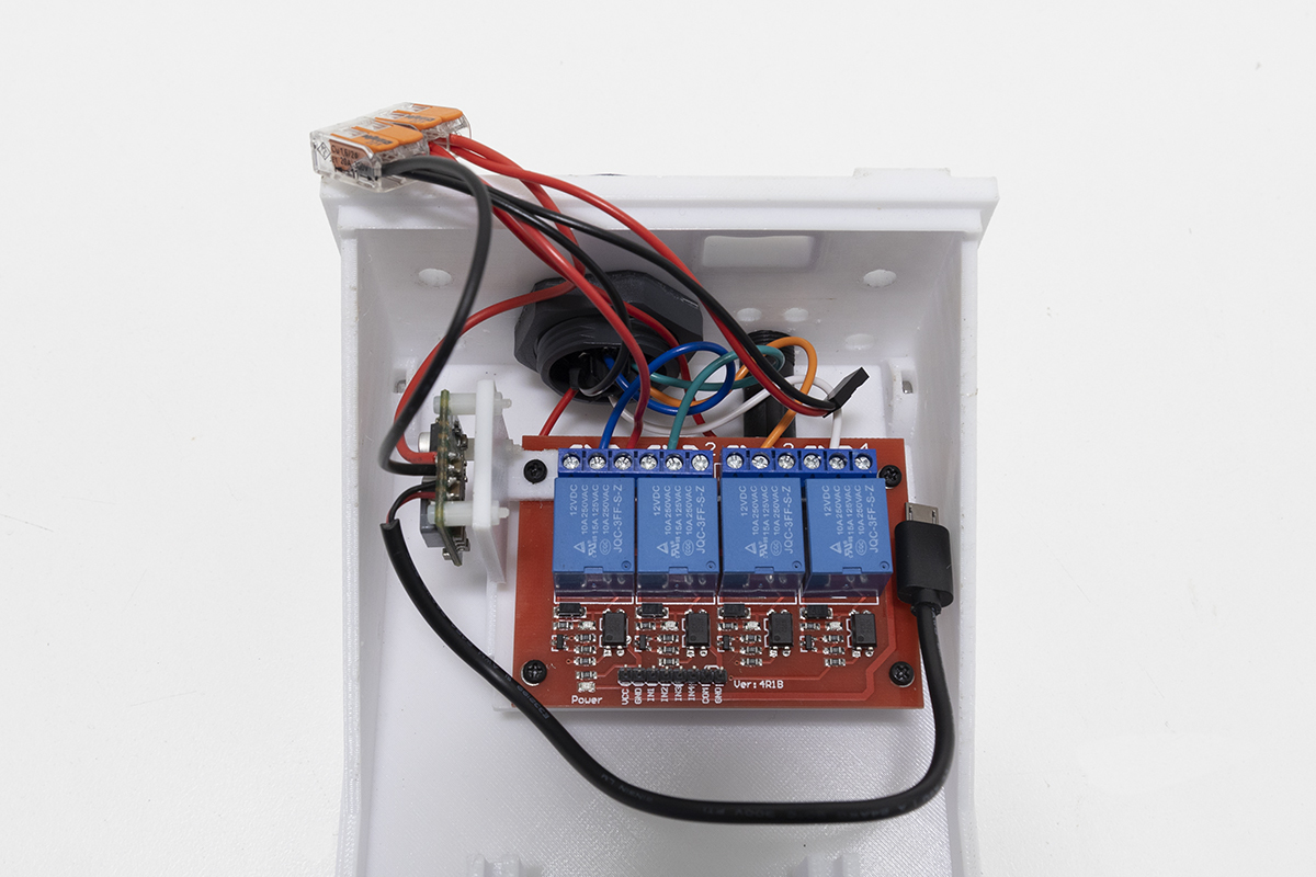
Step 5 - wiring the relay control board, voltage regulator, Wago 2-way blocks and Bulgin connector
Connect the relay control board to the Bulgin connector using the table in step 3 as a guide.
Relay Board Types
⚠️NOTE⚠️ Some relay control boards such as this on Amazon are ACTIVE on LOW. This means that the signal provided by the Raspberry Pi (a higher voltage) to activate a relay will instead turn the relay off. While this can be changed in the code, please consider purchasing HIGH level trigger ( e.g the board specified in the parts list) or adjustable trigger ( e.g. this board).
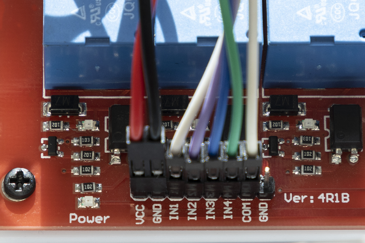
Next, connect red and black jumper wires to the VCC and GND header pins on the relay control board. Now choose one Wago block to be a 12V positive block and the second to be the negative or ground. To the positive block, connect the 12 V wire from the fuse (12V input from source), the 12 V input to the voltage regulator, the 12 V solenoid line from the relay board and the VCC line from the relay board to one of the two WAGO terminal blocks, twisting the wires together if necessary. Repeat with the second, negative WAGO terminal block, connecting the input ground line from the Bulgin connector, ground line from the voltage regulator and the GND black wire from the relay board.
Installed relay board |
Relay board wiring diagram |
Relay board wiring |
|---|---|---|
Step 6 - mounting Raspberry Pi and connecting power
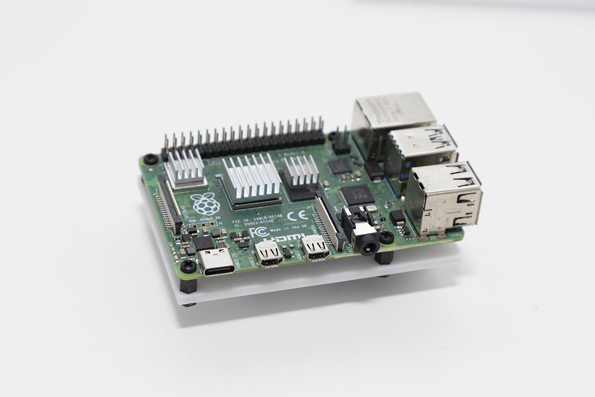
Attach the Raspberry Pi to the 3D printed mount using 2.5 mm standoffs. Install in the raised slots in the OWL base. Connect to micro USB power from the voltage regulator, using a micro USB to USB-C adaptor. Alternatively, the Raspberry Pi can be powered over the GPIO, however, this has not yet been implemented.
Raspberry Pi mount |
Raspberry Pi in OWL base |
|---|---|
|

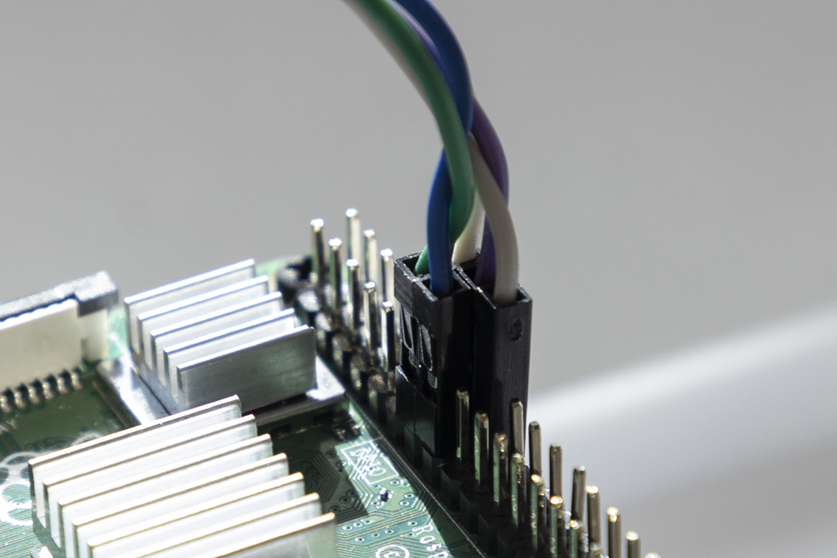
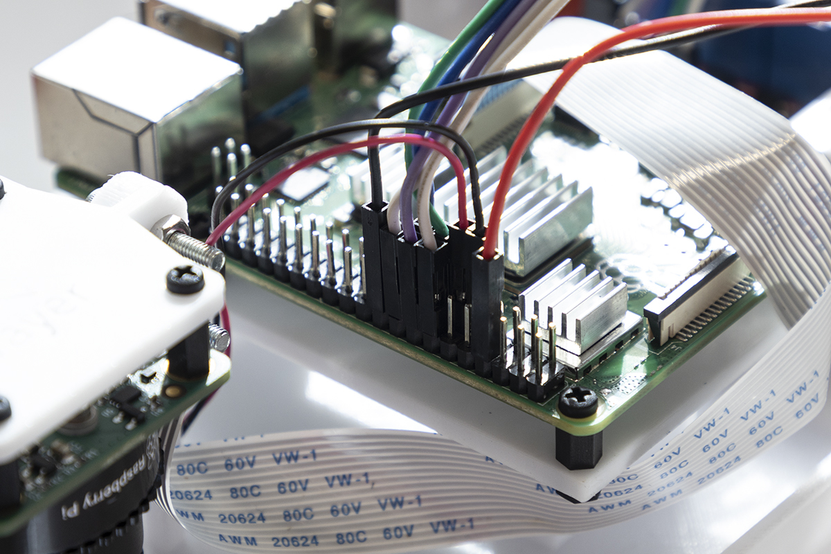
Step 7 - connecting GPIO pins
Connect the Raspberry Pi GPIO to the relay control board header pins, using the table below and the wiring diagram above as a guide:
The GPIO pins on the Raspberry Pi are not clearly labelled, so use this guide to help. Be careful when connecting these pins as incorrect wiring can shortcircuit/damage your Pi.

RPi GPIO pin |
Relay header pin |
|---|---|
13 |
IN1 |
14 |
COM |
15 |
IN2 |
16 |
IN3 |
18 |
IN4 |
Raspberry Pi GPIO pins |
Relay control board header pins |
|---|---|

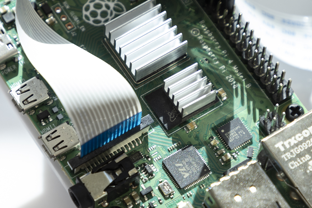
Step 8 - mounting and connecting camera
Connect one end of the CSI ribbon cable to the camera. We provide a mounting plate that can be used with both the HQ, Global Shutter or V2 cameras, however, we recommend the use of the HQ camera for improved image clarity. Attach the HQ camera to the 3D printed mount using 2.5 mm standoffs (or 2 mm standoffs if using the V2 camera). Ensuring that the CSI cable port on the camera is directed towards the Raspberry Pi, mount the camera inside the OWL case using four M3 standoffs (50 mm long for HQ camera; 20 mm long for V2 camera). Connect the other end of the CSI cable to the Raspberry Pi CSI camera port.
Before connecting the lens, please be aware the HQ camera comes with fitted a C-CS mount adapter which needs to be removed before fitting the 6mm lens. The image won’t focus unless the adapter is removed. More information is available below and in the HQ Camera Datasheet
How to remove the C-CS mount adapter:
HQ camera C-CS mount adapter |
Camera and adapter separated |
Lens fitted without adapter |
|---|---|---|
Mounting the HQ camera to the 3D printed mount:
HQ camera and mount |
HQ camera mounted in case |
|---|---|
|
|


Mounting the V2 camera to the 3D printed mount:
V2 camera and mount |
V2 camera mounted in case |
Raspberry Pi camera port |
|---|---|---|
|
|


The HQ lens will need to be focused, details below, once the software is correctly set up.
Step 9 - adding buzzer and LEDs
Mount the buzzer inside the OWL base using double sided mounting tape and connect the 5 V and ground wires to Raspberry Pi GPIO pins 7 and 9, respectively.
For simplicity we have used two 12V LEDs (which are just normal LEDs with a current limiting resistor included) for both the 5V TX/GND connection for Raspberry Pi status indication and also the 12V power connection. While 12 V will work fine on both, the 5 V connection will be dimmer. If you want to use a non-prepackaged, 3 mm LED for the 5V connection, you should solder a current limiting resistor to the LED to prevent damage to either the LED or the Rasperry Pi as described here. Install the 5 V LED inside the OWL base and connect the 5V and ground wire to GPIO pins 8 (TX pin) and 20 (GND pin), respectively. Install the 12 V LED inside the OWL base and connect the 12 V and GND wires to their respective WAGO terminal blocks.
Buzzer location |
LEDs in OWL base |
GPIO pins |
|---|---|---|
|

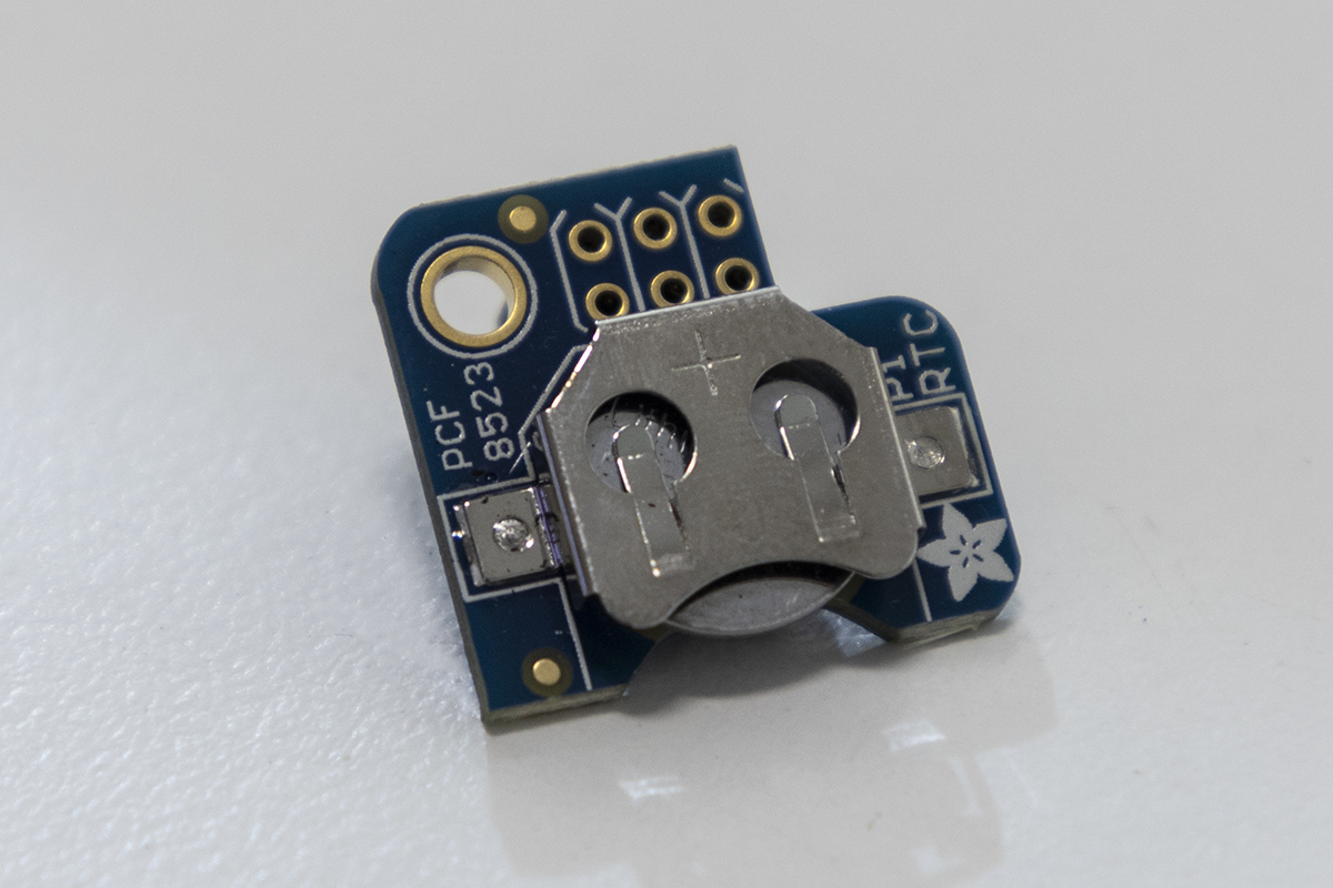
OPTIONAL STEP - adding real time clock module
Although optional, we recommend that you use a real time clock (RTC) module with the OWL system. This will enable the Raspberry Pi to hold the correct time when disconnected from power and the internet, and will be useful for debugging errors if they arise. The RTC uses a CR1220 button cell battery and sits on top of the Raspberry Pi using GPIO pins 1-6.
PiRTC module |
RTC installed on Raspberry Pi |
|---|---|
|

Step 10 - connecting mounting hardware and OWL cover
There are four 6.5 mm holes on the OWL base for mounting to a boom. Prior to installing the OWL cover, decide on a mounting solution suitable to your needs. In the photo below, we used 4 x M6 bolts. The cover of the OWL unit is secured with 4 x M3 nuts and bolts. Place M3 nuts into the slots in the OWL base. This can be fiddly and we suggest using tweezers, as shown below. Place the cover onto the base and secure using M3 bolts.
Mounting hardware |
Cover nuts |
Completed OWL unit |
|---|---|---|
|
|
|


Connecting Solenoids for Spot Spraying
Optional Step - connecting 12V solenoids
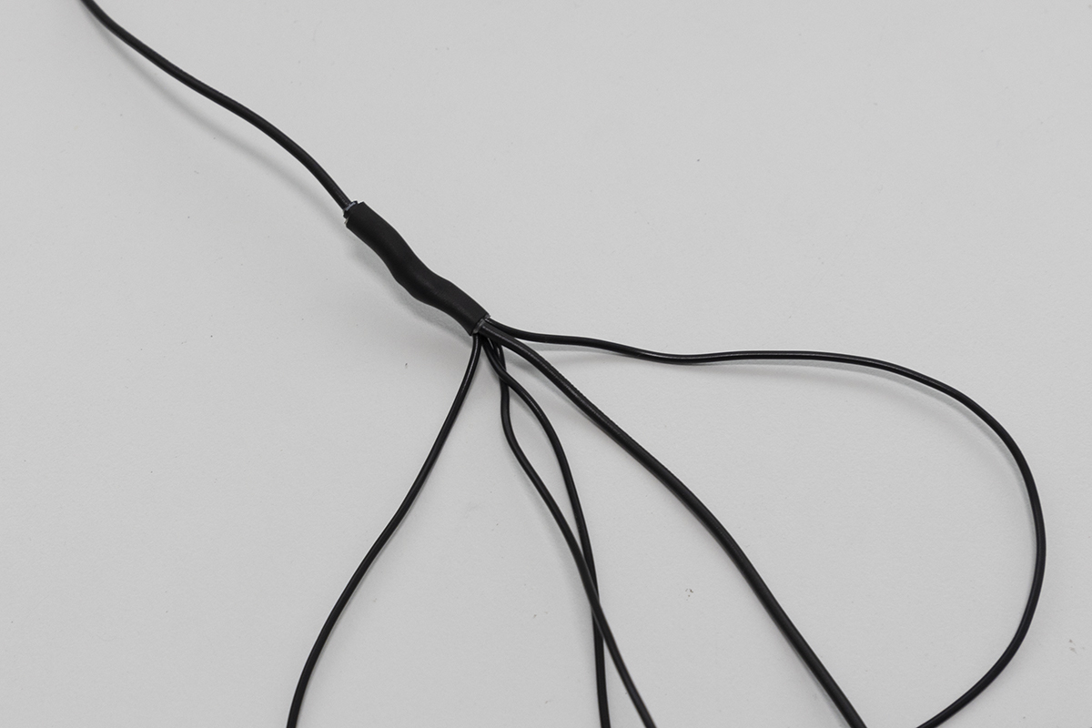
Once you have completed the setup, you now have the opportunity to wire up your own solenoids for spot spraying, targeted tillage, spot flaming or any other targeted weed control you can dream up. To do this, wire the GND wire of your device (it can be any wire if it’s a solenoid) to the ground pin on the Bulgin plug (the same wire used for the GND from the 12V power source) and wire the other to one of the blue, green, orange or white wires on pins 1 - 4. A wiring diagram is provided below. The easiest way to wire them together to the same GND wire is to create a six-way harness, where one end is connected to the plug, one of the five other wires to the source power GND and the remaining four to the solenoids or whatever devices you are driving.

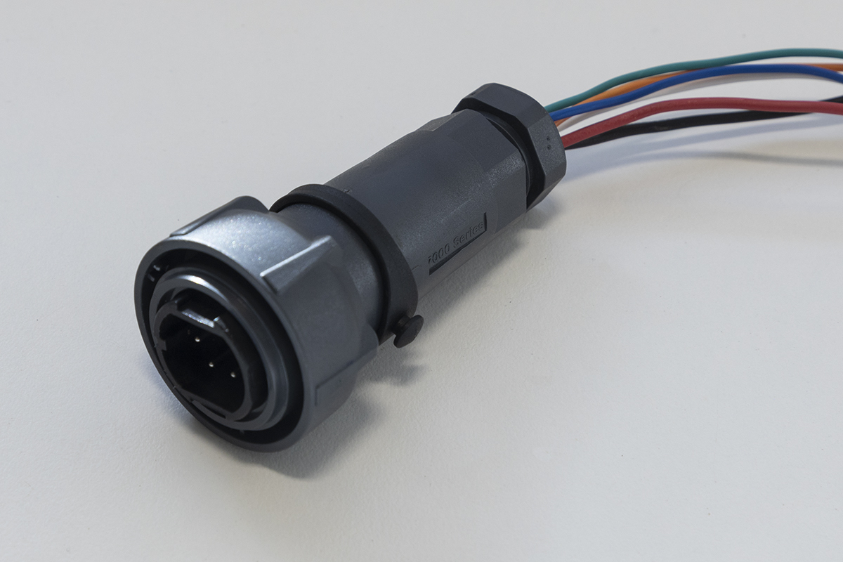
Bulgin plug |
Ground wiring harness |
|---|---|
Next Steps
Congratulations on completing your Original OWL hardware assembly! Here’s what to do next:
Install the OWL software on your Raspberry Pi to get your detection unit operational.
Configure detection sensitivity, relay timing, and other parameters for your specific use case.
Learn how to operate your OWL in the field, including mounting, alignment, and best practices.
Need replacement parts or want to print your own enclosure? Find all STL files and print settings here.